The mod500a2dv01 is a compact power module used in industrial I/O and motor control. This guide states the device specs, installation steps, wiring notes, and common fixes. It aims to help technicians and engineers assess the mod500a2dv01 quickly. The text uses direct language and clear steps to speed troubleshooting and reduce downtime.
Table of Contents
ToggleKey Takeaways
- The mod500a2dv01 is a compact DC power distribution module delivering isolated 12 V and 5 V outputs, ideal for industrial I/O and motor control applications.
- Proper installation requires mounting on a 35 mm DIN rail, secure wiring with correct torque, and adding a 10 A fuse on the input line to protect the system.
- When troubleshooting, check input voltage, inspect fuses, isolate load faults, and ensure adequate ventilation to prevent overheating.
- Routine maintenance includes inspecting terminals, cleaning dust, monitoring output voltages, and logging operating conditions every six months.
- For optimal performance, maintain input voltage between 20.5 V and 29 V, avoid overloading the 5 V rail beyond 80%, and use proper PPE and safety protocols during service.
- Selecting the right mod500a2dv01 variant depends on current requirements, mounting space, and redundancy needs, ensuring compatibility with existing PLC and control systems.
What The MOD500A2DV01 Is And Key Technical Specifications
The mod500a2dv01 is a DC power distribution module. It supplies regulated voltage to control boards and sensors. It measures 120 mm by 80 mm and weighs 210 grams. It accepts 24 V DC input and delivers isolated 12 V and 5 V outputs. It limits current to 8 A on the 12 V rail and 3 A on the 5 V rail. It includes short-circuit protection and thermal shutdown. It reports status with two front LEDs for power and fault. Data sheet ratings list operating temperature from -20°C to 70°C and storage temperature from -40°C to 85°C. It mounts on standard 35 mm DIN rail. The module supports screw terminals and pluggable headers for field wiring. The mod500a2dv01 carries CE and UL marks for industrial use.
Common Use Cases, Compatibility, And How To Choose The Right Variant
Technicians use the mod500a2dv01 in factory automation panels and remote I/O racks. Designers use it for small motor drives and sensor clusters. The module fits with most 24 V PLC systems and common fieldbus power supplies. It pairs with control cards that accept isolated 5 V and 12 V rails. Buyers should check rail currents, input polarity protection, and mounting style. They should confirm terminal type to match plant wiring. When systems require higher current, they should choose the mod500a2dv01 variant with dual 12 A outputs. When space is limited, they should pick the low-profile model. When redundancy is needed, they should order the parallel-ready version and add ORing diodes. The mod500a2dv01 family uses the same firmware and shares part numbers for spare inventory.
Step‑By‑Step Installation And Wiring Best Practices
Technicians should inspect the mod500a2dv01 before installation. They should check the label and serial number. They should turn off all power before wiring. They should mount the module on a clean 35 mm DIN rail. They should tighten the terminal screws to the specified torque listed in the manual. They should connect the 24 V DC input to the V+ and V- input terminals. They should ground the chassis to the earth terminal. They should route signal wires separate from power cables. They should use ferrules on stranded conductors. They should add a 10 A fuse on the input line to protect upstream wiring. They should wire the 5 V and 12 V outputs to the loads and verify polarity. They should power the system and check the green power LED. They should measure the output voltages under load to confirm proper regulation. They should label the module in the panel and record the serial number for maintenance. The mod500a2dv01 will need no firmware steps for basic operation.
Diagnosing And Fixing The Most Frequent Problems
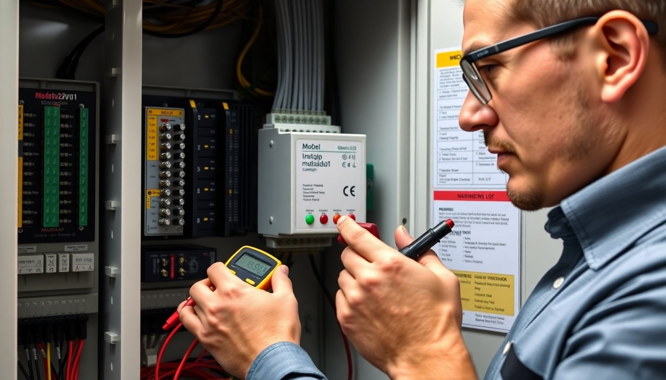
When the mod500a2dv01 fails to power, technicians should confirm the input supply. They should measure 24 V at the input terminals. They should inspect the input fuse and replace a blown fuse with the correct type. When the fault LED glows, they should check for output short circuits. They should disconnect loads and reapply power. If the unit resumes, they should isolate the failed load. When outputs show low voltage, they should measure current draw. They should compare measured current to the mod500a2dv01 rating. When the module overheats, they should check ventilation and ambient temperature. They should remove nearby heat sources and add air circulation. When the module trips on startup, they should check for inrush currents from capacitive loads. They should add a soft-start or limit inrush with an NTC or resistor. When status LEDs are ambiguous, they should consult the data sheet LED table. If the mod500a2dv01 shows repeated failures, they should replace the unit and send the failed unit for factory test.
Routine Maintenance, Safety Considerations, And Performance Tips
Maintenance teams should inspect the mod500a2dv01 every six months. They should check terminal tightness and clean dust from vents. They should measure output voltages and note drift. They should record operating hours and temperature cycles in the log. They should avoid installing the module near high-vibration sources. They should secure wiring to reduce stress on terminals. For safety, they should isolate power before any work and verify zero volts with a meter. They should use PPE when working inside panels. For performance, they should keep the input voltage within 20.5 V to 29 V range to prevent regulation issues. They should avoid loading the 5 V rail above 80% of its rating. They should use separate fuses per output when loads share common faults. They should use the mod500a2dv01 spare part number for replacements to ensure fit and certification. They should update spare stocks based on failure trends and critical system needs.